Combining a Reference Signal with L-Band Traffic
Copper v Integrated RF over Fiber (RFoF)
This piece discusses two approaches to distributing an L-band traffic signal and reference signal. The two approaches are:
- Copper coax
- Integrated RF over fiber solution
The downlink receives traffic but transmits a reference signal from the control room to the remote (antenna) end in order to synchronize the outdoor equipment with the modem. The uplink transmits both traffic and the reference signal from the control room to the remote end.
Signal power levels
A traffic signal is low power – typically -20 to -60dBm. In contrast, the reference signal is usually transmitted at high power (e.g. +12dBm) to minimize the impact of interference with the synchronization.
Which reference frequency?
The reference frequency is usually assumed to be 10MHz. However, in reality it can range from as low as 5MHz up to 50MHz. A higher frequency reference signal offers a greater scope for accuracy – if required.
Solution 1 – Copper coax
Many satcom engineers wouldn’t give reference signal transmission a second thought. For a short range VSAT installation, the signal would be combined with the traffic signal over coax. This is the simple, low cost solution. However, copper is not a good conductor of high frequency because skin effects cause signal degradation. Consequently, copper struggles to support L-band link distances more than around 300ft/100m. Also, a copper link can easily be ‘sniffed’ using a current clamp which makes it unsuitable for applications requiring a secure link.
Advantages: Lower cost, simplicity
Disadvantages: Short link distance, not secure
Solution 2 – Integrated RF over fiber solution
Like coax, RF over fiber can combine traffic and reference signals on the same link. The two are transported on different optical wavelengths to minimize intermodulation. One significant disadvantage however, is that RFoF links are inherently mono-directional. Therefore two links are required to support uplink and downlink and this impacts the cost.
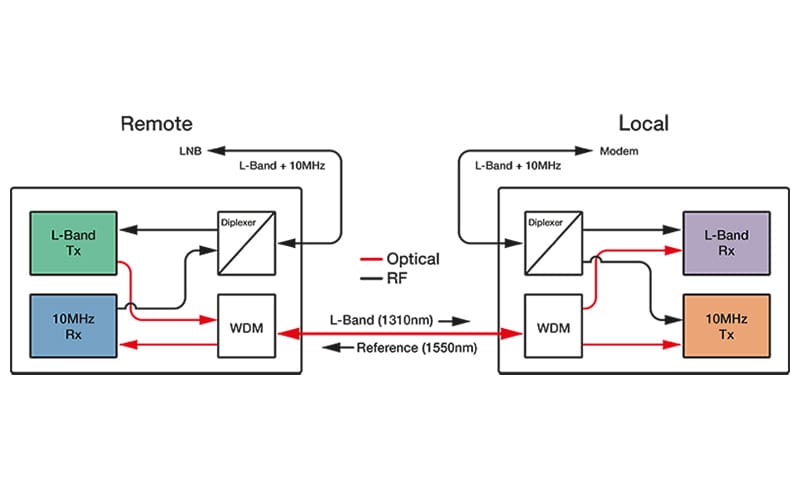
Figure 1 shows a downlink solution where an RFoF module at the remote end receives the traffic from the LNB and converts to an optical signal for transmission to the control room. Simultaneously the module receives the reference signal in optical form and converts to an electrical signal which can be supplied to the LNB or BUC. At the local end, a corresponding RFoF module sends the reference signal and accepts the traffic signal. This bi-directional solution is possible because the traffic and reference signals use different wavelengths. For the uplink, the situation is similar except the direction of the traffic signal is reversed.
Since the losses of fiber are very low, the link distance can be much longer than is possible with copper coax. A standard RFoF link can typically support up to 10km. Fiber is almost impossible to tap without a catastrophic loss of signal at the receive end therefore this approach can be used for secure applications. Unlike copper, fiber also provides a flat frequency response and so does not require slope compensation.
RFoF links also offer the potential to remotely control the LNB using a 22kHz tone and switching voltages.
Advantages: Long link distances, secure, flat frequency response, LNB control
Disadvantages: Higher cost, more complex