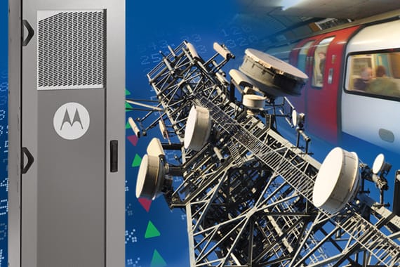
RF over Fiber GNSS Signal Extension and Distribution
This guide discusses the advantages of using ViaLiteHD RF over Fiber (RFoF) for GNSS signal extension and distribution, and the practical considerations of designing such a system.
Download a PDF copy of this Guide.
Growth in need for GNSS antenna and distribution
Over recent years we have witnessed dramatic market demand for GPS and GNSS enabled devices for both mobile and fixed applications including Navigation and Precision Network Timing (PNT). High-rise buildings, hard to reach underground locations, and complex engineering structures like ships, can often require the routing and distribution of GNSS signals throughout.
Particularly in the data center and financial service hosting business, the need for GNSS enabled PNT has seen large expansion and often requires distribution to many PNT endpoints. The introduction of automated and algorithmic trading can create thousands of trades per second and these trades need to be timestamped against a common time standard, hence the need for PNT. This is an industry that is also heavily regulated, and the strict timing accuracy has been mandated in Europe through the MiFID II (Markets in Financial Instruments Directive II) and clock synchronization standard RTS 25; with similar requirements in other regions (e.g. SOX in North America).
High frequency trading timestamp
| Maximum divergence from UTC | Granularity |
|---|---|
| <100 microseconds | 1 microsecond |
Routing GNSS signals using RF over fiber rather than coax
When cable lengths are short, for instance less than 50 meters, coax can often be a reasonable solution to connect GNSS antenna through to GNSS user equipment like PNTs or navigational systems. But when we start using lengths longer than this or need to split the GNSS signal out to many end-points then we start seeing the limitations of coax quite quickly.
Fiber optic losses can typically be a thousand times smaller than a good quality piece of coax. For this reason RFoF systems regularly route RF signals in the tens of kilometers with minimal signal loss. Fiber optic also provides considerable saving in terms of weight and space saving. By introducing multiplexing technologies, the space saving can be increased even further. Finally, GNSS signals often start with an antenna in the open and exposed outside environment; RFoF provides inherent lightning immunity to expensive end-user equipment.

Designing a simple GNSS link extension for Precision Network Timing
If we start by taking a simple and common-use case: a GNSS antenna on a rooftop needs to be connected to a PNT which is located some distance away or in a hard to reach place. If we used a piece of coax, this would also route DC power to the active antenna and the PNT would be able to sense an open circuit and show an alarm. So, our RFoF system also needs to provide active DC feed to the GNSS antenna and maintain the alarm integrity to indicate a break in the antenna link. The ViaLiteHD range supports both of these requirements, but also builds in the advantages of fiber link extension and distribution.
| PNT Vendor | Typical GNSS antenna DC feed |
|---|---|
| EndRun, Spectracom / Orolia | +5 V |
| Microsemi | +9 to +12 V |
| Meinberg | +15 V |
Putting the system together, the GNSS antenna is connected to the ViaLiteHD RF to Optical transmitter via a coax and optional lightning arrestor. The transmitter also includes a DC supply feed to the antenna. Single mode fiber is then used to connect the transmitter to the ViaLiteHD Optical to RF receiver which is located near the end-user PNT. The ViaLiteHD receiver is connected to the PNT GNSS antenna port. The receiver also provides a simulated antenna loading to the PNT, to simulate connection to an active antenna. In the ViaLite system if there is a problem with the GNSS antenna or a break in connection, the loading function to the PNT can be removed and hence correctly indicates an alarm.
In the diagram, ViaLiteHD Blue OEM modules are displayed. For larger systems with more links or systems requiring power supply redundancy or monitoring SNMP, ViaLite also offers 1U and 3U rack chassis units, dual redundant power supplies, SNMP cards and a variety of other accessories to split the signal optically or in RF.

Putting together the RF Link Budget and Time Delay Budget
ViaLite can design a RF Link Budget and Time Delay Budget for most RF communication systems. In the simple example below, we start with the typical signal power of a GNSS signal, as seen near open ground, which is typically very small and around -130 dBm. The GNSS active antenna LNA can provide +30 dB to +40 dB of amplification before the signal passes through the lightning arrestor and into the ViaLiteHD transmitter.
The transmitter and receiver pair are set – in this example – to give a combined signal gain of +9 dB. The fiber cable is 50 meters long so gives negligible losses of ~0.2 dB. – When we convert from optical losses to equivalent RF losses, we multiply the optical losses by a factor of two.
| RF input (GNSS roof top signal) | -130 dBm |
| Active antenna gain | 40 dB |
| Coax (5 m @ 0.4 dB/m) gain | -2 dB |
| Lightning arrestor gain | -3 dB |
| Coax (5 m @ 0.4 dB/m) gain | -2 dB |
| ViaLite Tx (E/O) | -5 dB |
| SM FO cable (50 m @ 0.0002 dB/m) | -0.2 dB |
| ViaLite Rx (O/E) | 14 dB |
| Coax (1 m @ 0.4 dB/m) gain | -0.4 dB |
| RF output (to PNT server) | -88.6 dBm |
Bringing together the signal powers and system losses and gains, we can construct the RF Link Budget as seen in the table. In this example, the signal power entering the PNT using RFoF is a healthy -88 dBm. If we had used an equivalent coax, the signal would be down at -118 dBm.
In PNT applications it is also useful to calculate the Time Delay Budget from the GNSS antenna through to the PNT antenna input port. This delay can be entered into the PNT to improve its accuracy in absolute terms. RFoF is an analog directly modulated technology; this enables a very low conversion delay in the transmitter and receivers. In ViaLiteHD, the conversion is typically only 4.5 ns per module. The Time Delay Budget is largely driven by link length.
Time Delay Budget
| System element | Quantity | Delay per meter or device (ns) | Total Delay (ns) |
|---|---|---|---|
| Coax #1, 5 m | 5 | 3.90 | 19.50 |
| Coax #2, 5 m | 5 | 3.90 | 19.50 |
| ViaLite Tx & Rx pair | 1 | 9.00 | 9.00 |
| SM FO cable, 50 m | 50 | 4.90 | 245.00 |
| Coax #3, 1 m | 1 | 3.90 | 3.90 |
| Total time delay (ns) | 296.90 ns |
GNSS signal distribution methods and products
This example so far has described a simple point-to-point link extension for a single PNT connected to a single GNSS roof-top antenna. Customer applications, however, are often more varied and demanding in terms of the number of end-points and link length. The ViaLiteHD range includes a number of supporting products which solve these requirements.
For applications where “wide area” GNSS signal distribution is required (i.e. more than 20 meters between each end-point) or where the end-points are compartmentalized, an optical splitter is advised. This places a splitter after the ViaLiteHD transmitter and effectively splits the optical signal into multiple outputs for wide area routing. A ViaLiteHD receiver is used at each end-point. Splitters can typically go up to 64 output ports; as you increase the number of ports, optical losses increase. ViaLite‘s product range also includes a Multizone Lossless Optical Splitter which removes these losses, making the splitter 0 dB.

For applications where “local-area” GNSS signal distribution is required (i.e. there’s typically less than 20 meters from the receiver to the endpoints, often in the same room) then it is safe to use the more conventional RF splitter connected to the output of the ViaLiteHD receiver. Also in the ViaLite product range we have a 1U chassis product with an integrated RF splitter which can support 8 to 32 RF ports, as well as the ViaLiteHD receiver, powers supplies and even the SNMP.

Final words
Hopefully this guide has helped describe the wonderful benefits RFoF can bring in the world of GNSS signal extension and distribution. Using sound RF design techniques, high quality RFoF links, together with innovative wide area and local distribution products from ViaLite, reliable and resilient links can be employed in the most demanding industrial, data center, maritime and laboratory applications.
Written by Director of Sales, Richard Jacklin