Install and Setup a Fiber Link
In 10 steps…
- Remove dust covers from your cross site fiber (or patch leads) and the connectors on the RF over fiber links.
- Clean the cross-site cable; dirty fibers cause performance issues.
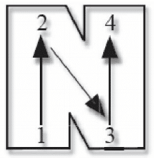
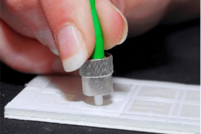
a) Peel the plastic cover from an unused “N” cleaning pad.
b) Hold the connector between your thumb and forefinger. Clean the connector using firm pressure by swiping in a pendulum motion through each segment of the “N” shape, following the diagram. Do not swipe over the same space twice.
- Insert the fiber into the equipment ensuring that any keyway is aligned.
- To connect SC/APC optical connectors:
Remove the connector protective cover. Align the connector keyway slot in the adaptor to the key of the plug. Gently push the plug into the adapter until a click is heard and the connector locks. - To connect E2000/APC optical connectors:
Gently push the plug into the adapter until a click is heard and the connector locks. - All ViaLite FC/APC equipment use narrow key FC/APC connectors, these are not compatible with wide key FC/APC. To connect FC/APC optical connectors:
Remove the protective cover and align the white ceramic center ferrule on the cable connector with the mating receptacle. There is a key on the side of the ferrule, which must match the keyway slot in the receptacle shroud. When they are aligned, gently push the plug home and finger-tighten the knurled collet nut onto the threaded receptacle.
- Care needs to be taken with bends in the fiber; the minimum Bend Radius of a simplex patch cable is typically 30mm. This will introduce a very small increase in loss – 0.05dB.
- Switch on the equipment at both ends of the link. If any LED is red or flashing red then check fiber connections for cleanliness and correct fitment or continuity in the fiber path.
- Connect all RF cables and then allow the equipment to warm-up for 15 minutes.
- Ensure that the RF power into the transmitter module is set to optimum for your system.
- Calculate the approximate optical attenuation in the fiber path, including patches (0.2dB for each) and 0.4dB per km for a 1310nm laser. The RF loss is 2x the calculated optical loss.
- Adjust gain control via the SNMP or the dip switches on the card to cancel out the cross site losses.
- If the loss is still much higher than expected (>3dB), the most likely explanation is dirt on the optical connectors. If this is the case, clean each connection in turn.
For queries, please contact our dedicated Technical Support team, by emailing technicalsupport@vialite.com or by phoning +44 (0) 1793 784389.

 +44 (0) 1793 784389
 +1 (855) 4-VIALITE
 sales@vialite.com


