How to Solve Technical Difficulties with RF over Fiber Equipment
This general troubleshooting guide is designed to identify common technical issues found when using RF over fiber equipment and provide important information to help resolve issues and keep your system in good working order.
Contents
- ViaLiteHD product frequency bands
- Datasheets
- ViaLite system and chassis reports
- Monitoring and Control (M&C) access – HRC products
- What to do if your HRC card or module does not show up in the M&C software or web GUI
- GPS module alarms
- Manual configuration of LNA/LNB and BUC feeds for plug-in modules
- General link optimization tips including selecting and setting gain
1. ViaLiteHD product frequency bands
To ensure you are operating within the product specifications for optimized performance, it is important to check your frequencies when troubleshooting issues. The below frequency ranges offer guaranteed specifications shown in the product datasheets, while operating outside of this range may mean higher losses and a negative impact on product performance.
| Band | Name | Frequency Range |
|---|---|---|
| V | Broadcast | 100 – 1000 MHz |
| T | Timing | 10 kHz – 50 MHz |
| B | IF | 70 – 140 MHz (10 – 200 MHz) |
| D | DVB | 470 – 860 MHz |
| N | VHF/UHF | 10 MHz – 1 GHz |
| P | Radar | 10 – 1350 MHz |
| L | L-Band HTS | 700 – 2450 MHz |
| J | L-Band HTS | 700 – 2450 MHz + 10 MHz Timing (Rx) |
| K | L-Band HTS | 700 – 2450 MHz + 10 MHz Timing (Tx) |
| G | GPS | 1000 – 1800 MHz |
| S | Wideband | 10 MHz – 3 GHz |
| W | Extra-Wideband | 10 MHz – 4.2 GHz |
| U | Ultra-Wideband | 2 kHz – 4.2 GHz |
| Y | Mil-Aero | 10 MHz – 6 GHz |
| C | C-Band | 500 MHz – 7.5 GHz (3.1 – 7.6 GHz) |
2. Datasheets
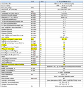
The ViaLite datasheets contain important information regarding nominal input power, P1dB, IP3, maximum input without damage and other important information. When setting up your system, the datasheets should always be referenced in the first instance to ensure operational levels are suitable for the selected equipment. You can find all the product datasheets on the respective product pages, under the Downloads tabs.
A nominal input power of around 8 dB below the P1dB should be used. This can vary, but if it is too high then clipping will occur from compression.
3. ViaLite system and chassis reports
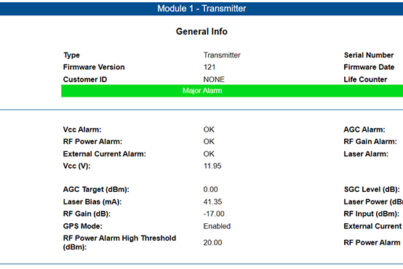
The ViaLite reports, available in the M&C software or Web GUI, provide a wealth of information regarding the product settings, alarm information, optical levels and much more. In the event an issue with the equipment, or an alarm, you can generate the reports and check all of the values reported are as expected. These reports can be emailed to customer support for further investigation in the event of a failure.
To generate a report from the M&C software or Web GUI, go to the top banner and select reports. This will bring up the System Reports Menu.
There are three levels of report:
- Chassis (system) report
- Event log
- ViaLite system report
The chassis report is referred to as a system report and appears as the first option in the reports section. This will give you information on all of the slots, with details on Received Light Levels (RLL), power, gains and more.
The event log shows what has been happening with the chassis, such as any alarms activated. A limited number of entries are stored in the log.
The ViaLite system report is designed as a high-level report that can only be opened by the ViaLite customer support team. This can provide detailed information on any historical occurrences in the chassis.
4. Monitoring and Control (M&C) access – HRC products
There are a few M&C module variants available to monitor and control the ViaLite equipment, depending upon the enclosure type and the support required. To assist in connecting to these M&C modules, a guide has been provided with detailed instructions, including access passwords and the differences in connecting to the legacy (unsupported) HRC-1, HRC-3, and the ODE-MINI and ODE-A4 Site Controller, the GPS Splitter Rack and Mil-Aero OEM’s.
Click here to go to the M&C guide.
5. What to do if your card or module does not show up in the M&C software or Web GUI
Occasionally, one of your rack chassis cards or M&C modules may not show up in the M&C software or Web GUI. The mating connector at the back of the card not “engaging” fully with the chassis connector usually causes this. This can be resolved by releasing the card slightly, then re-inserting into the slot. You can then check for polling of the cards from the HRC card. If the amber LED is not lighting up and flashing periodically, then it is not being polled.
The legacy HRC-1 card is no longer supported. Some of the newer ViaLiteHD cards will not be recognized by this legacy M&C card. If you have cards not showing up in the GUI and the HRC-1 controller is being used, please contact ViaLite for information on upgrading to the HRC-3.
If the card does not show up in the chassis and the card and M&C module have been re-seated and updated (as above), please contact ViaLite customer support to confirm if the card type is supported by the HRC-1, or if there is a fault. For supported products, please refer to the comparison chart here.
6. GPS module alarms
GPS/GNSS modules are fitted with a system where there will be an alarm indicated in the event of no loading from the GPS antenna. Unless GPS mode is disabled in the module, the transmitter (Tx) will not be enabled until this loading is detected. When power is applied to the GPS Tx module, you should see a red LED on the unit. Once connected to the GPS antenna, the LED should go green. If the LED stays red, this indicates a probable fault with the GPS antenna. A full guide is available on the GPS antenna loading alarm states.
GPS antennas are usually supplied with a 5 V or 12 V powering requirement. When selecting a GPS module it is important to ensure it is suitable for the GPS antenna.
7. Manual configuration of LNA/LNB and BUC feeds for plug-in modules
In the event of issues with the LNA/LNB and BUC feeds, check the manual configuration on the cards.
Some modules can be configured by either a jumper or a switch, to provide an LNA/LNB or BUC feed either from an internally generated voltage or from the external rear connector in the chassis. Details for this setup can be found in the RF link handbook, section 2.7.
8. General link optimization tips including selecting and setting gain
Adjusting the gain can affect the Minimum Detectable Signal (MDS) and P1dB levels. For example, if you increase transmitter gain, this lowers the P1dB and MDS levels. Conversely, decreasing transmitter gain increases the P1dB and MDS levels. This effect on MDS and P1dB needs to be considered when compensating for fiber losses, as well as the signal levels used in the RF over fiber system. For more information on the importance of gain in RF over fiber, click here for the guide.
Setting gain
In order to set gain within the ViaLiteHD rack cards, there are three options.
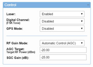
SGC (Software Gain Control) is activated by accessing the M&C software or Web GUI and selecting the SGC option in the relevant RF card. The level of software gain can then be set, within the limits of the gain range. To see the maximum and minimum SGC levels permissible, hover the cursor over the SGC gain field and the limits will be displayed.
AGC (Automatic Gain Control) can also be selected within the M&C software or Web GUI in the same manner as for SGC. The AGC function must be selected in the gain control field. See the AGC guide here.
MGC (Manual Gain Control) can only be set by selecting “MGC=ON” with the DIP switches on the side of the RF card. The level of gain can also be set by selecting the relevant gain switches to ON. MGC overrides SGC & AGC, so if the DIP Switch is set to MGC=ON, then SGC and AGC will have no effect. If selecting SGC or AGC does not appear to have any effect on the signal, always check that the MGC DIP switches are set to off.
In the gain control field in the M&C software or Web GUI, there is also a factory default setting. If this is selected, then the original factory setting gain level will be used. SGC and AGC settings will not have any effect if this is set to factory default.
Thermal effects on gain
The gain of a ViaLiteHD module will reduce as temperature increases. This is detailed in the RF Link handbook, section 3.16.1.
For any technical issues not covered by this guide, please contact our dedicated Technical Support team, by emailing technicalsupport@vialite.com or by phoning +44 (0) 1793 784389.

 +44 (0) 1793 784389
 +1 (855) 4-VIALITE
 sales@vialite.com
 Click to expand
 Click to expand
 Click to expand
 Click to expand
 Click to expand

