How to Connect to the ViaLite Monitoring & Control (M&C) Modules
This guide will explain how to connect to following ViaLite Monitoring & Control (M&C) Module products:
Download this Guide in PDF format.
HRC-1
Note* The HRC-1 is the legacy M&C card and is no longer supported. The HRC-1 went end of life in September 2020. If you are using the legacy HRC-1 controller, please contact ViaLite to review upgrade and connection options.
HRC-3
If you don’t know the IP address:
Step 1 – Connect a serial cable between your laptop/PC and the Micro USB serial port on the front of the HRC-3 (either the one supplied with the HRC-3 or any Micro USB to USB data cable).
Step 2 – Go to Device Manager on your PC and check which COM port is in use (in the below example this is ‘COM12’).

Step 3 – Open PuTTY, set the connection to ‘Serial’ and update the COM port in the ‘Serial line’ field.

Step 4 – Click ‘Open’ and you will see the CMD window appear with the ViaLite login screen.

Step 5 – Log in to the CMD window with the relevant username and password details (see Table 1 at the end of this document for details).
Step 6 – Type ? to see all available commands and use sys_info to see the system information, including all IP settings.
Step 7 – Once you have confirmed the IP address, select ‘Exit’ to close the CMD window and restore the system for use.
If you know the IP address:
Step 1 – Open a web browser (e.g. Chrome) and type the IP address into the address field – you will then be presented with the ViaLite Web and SNMP Controller.
Step 2 – Log in using the relevant username and password (see Table 1 at the end of this document).
Step 3 – If the system has connected to the HRC-3 correctly, you should also see the HRC-3 serial number displayed above the login boxes.

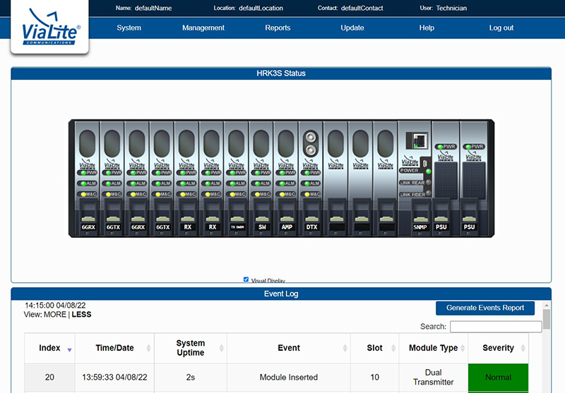
Step 4 – Now you will be presented with the Web GUI, where you can interrogate the individual card settings, monitor alarms and set up Tx and Rx gains.
ODE-MINI & ODE-A4
Step 1 – In order to connect to the ODE-MINI/ODE-A4, you will need to know the IP address of the unit.
- If the IP address is changed, this must be recorded for future access – losing the IP address may cause connection issues.
- If the IP address has not been set, the default IP address will be 10.0.0.104
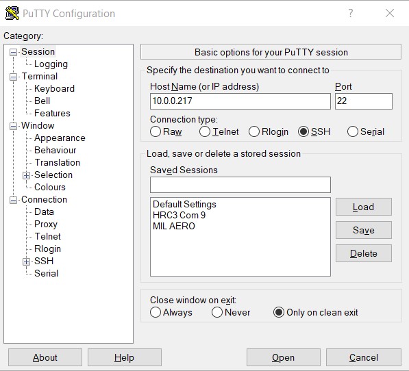
Step 2 – In order to change or adjust the network settings, time and date and other features, it will be necessary to connect to the system and access the control menu. To do this, open a PuTTY session, select ‘SSH’, and enter the IP address into the address bar. In the below example, the IP address is 10.0.0.217.
Step 3 – Click ‘Open’ and you will see the CMD window appear with the ViaLite login screen.
Step 4 – Log in to the CMD window with the relevant username and password details (see Table 1 at the end of this document). In this example, the username is Technician and the password is tech.
Step 5 – Type ? to see all available commands.

Step 6 – Select sys_info to see the current settings.
If you are updating the IP address of the ODE, please ensure you update the ip_gateway and the ip_netmask BEFORE updating the ip_Address.
Updating the IP Address is dynamic, and will take effect immediately. Updating this ahead of the netmask and gateway may cause the ODE to become unresponsive.
Step 7 – When all settings have been adjusted as required, ensure you use the command ‘Exit’ to leave the CMD window. Failure to use this command may cause connection problems with the Web GUI.
Step 8 – To access the Web GUI, open a web browser (e.g. Chrome) and type the IP address into the address bar, this will bring up the Web GUI – you will then be presented with the ViaLite Web and SNMP Controller.
Step 9 – Log in using the relevant username and password details (see Table 1 at the end of this document).
Step 10 – If the system has connected to the ODE-MINI/ODE-A4 correctly, you should also see the product’s serial number displayed above the login boxes.

Step 11 – Now you will be presented with the Web GUI, where you can interrogate the individual card settings, monitor alarms and set up Tx and Rx gains.

GPS Splitter Rack
The GPS Splitter Rack is a 1U rack GPS receiver solution. This chassis can take up to 2 x GPS receiver cards. By utilizing dual Rx GPS modules, 4 GPS receiver packages can be used.
The GPS Splitter Rack is fitted with an internal version of the HRC M&C card to provide full M&C control of the GPS Rx cards installed, allowing gain adjustments and control of all available features.
Step 1 – In order to access the HRC card within the GPS Splitter Rack, you will need to know the IP address of the unit.
- If the IP address is changed, this must be recorded for future access – losing the IP address may cause connection issues (see reset below).
- If the IP address has not been set, the default IP address will be 10.0.0.104
Step 2 – Open a web browser window (e.g. Chrome) and type the IP address into the address bar. You should see the Web GUI login window.
Step 3 – Log in using the relevant username and password details (see Table 1 at the end of this document). The Web GUI will now be available where the card gains and features can be adjusted. In order to access the individual card menus, click on the relevant card in the image to access that card’s features.
Step 4 – To access the HRC card within, click on the ‘RJ45’ port in the image to bring up the HRC card properties.

Step 5 – To connect to the M&C card and access the control menu where you can change or adjust the network settings, time and date and other features, it will be necessary to connect to the system and access the control menu. To do this, open a PuTTY session, select ‘SSH’ and enter the IP address into the address bar. In the below example, the IP address is 10.0.0.217.
Step 6 – Click ‘Open’ and you will see the CMD window appear with the ViaLite login screen.
Step 7 – Log in to the CMD window with the relevant username and password details (see Table 1 at the end of this document).
Step 8 – When all settings have been adjusted as required, use the command ‘Exit’ to come out of the session and close the CMD window.
Please note: In the event that the IP address is lost or unknown on the GPS Splitter Rack, there is a reset button on the rear of the chassis:
- The reset button is located on the rear panel below J1 – under all normal operating circumstances, use of this will not be required.
- Short pressing the reset button will reboot the module, while long pressing the reset button will reset the module back to the factory default settings.
- In order to activate the reset, a small object (for example, a bent paperclip) should be used to depress the button. The button has positive feedback and the user should feel it activating.
Mil-Aero OEMs (Black IP Rated and Blue Modules)
Step 1 – In order to connect to the Mil-Aero OEMs, open up a PuTTY session.
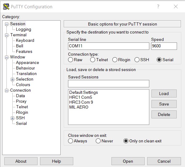
Step 2 – Select the relevant COM port (check Device Manager on your PC to confirm) and enter this in the ‘Serial line’ field.
Step 3 – Select ‘Serial’ and put 9600 in the ‘Speed’ field.
Step 4 – Click ‘Open’ and you will see the CMD window where individual gains and features can be set. In the below example, it can be seen that the BiasT voltage is being adjusted and switched off.

The full command set for the Mil-Aero OEMs is available by clicking here, or alternatively, the full command set can be viewed as a PDF by clicking here.
Access Passwords*
| Username | Password | |||
|---|---|---|---|---|
| Guest | guest | |||
| Admin | admin | |||
| Technician | tech |
Further Assistance
In the event that you are unable to connect for any reason, please contact our dedicated Technical Support team, by emailing technicalsupport@vialite.com or by phoning +44 (0) 1793 784389.