System Designer Guide
ViaLite’s System Designer tool has been developed to assist users in designing complex RF over fiber Satcom systems using multiple DWDM products. Users can use the tool to predict and validate the performance of their end-to-end solutions.
Download this Guide in PDF format.
Steps
1) To start, the user should log into their account on the System Designer tool: https://systemdesigner.vialite.com/index.html. We advise that Google Chrome is used to run the System Designer.
Once logged into their account, the user can start the process of building their system. The user interface of the System Designer tool is similar to that of Microsoft Visio.
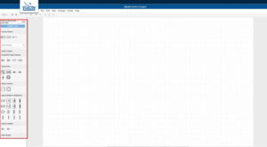
2) Users are able to select the different components and drag and drop them into the drawing area in order to design their system. By adding components into the system, the user is able to replicate a current live system or an intended system design.The relevant components are located on the left hand side of the drawing area in a tool pallet as shown below.
3) The components must be connected by wires, which can be dragged from one component to another, between the green indicator points. When a valid connection has been made, these connection points will become part of the link budget calculation.
Please note that wires and components that simply overlay other wires and components do not make a connection.
4) Alterations can also be made to each component to make the system as accurate as possible. As shown in the image below, for the RF Source components, the ID, System Temperature, Source Power, Source Noise and the IMD can be configured.
With other components, users can configure other aspects, including the dB gain, the variation of the component, and how many spares will be required. When configuring fiber optic cables, users can select the length of the cables in kilometers to replicate their system.
5) Once the user has completed the design of their system, the “Analyze Links” button, which can be found on the left, above the components, produces a PDF document of the system.In the bottom right corner of the first page is the title block, which includes the drawing title, date, author etc.In the bottom left corner is the analysis outputs of the system, which includes the expected link performance. Below the border on the left is the version of the tool.
6) Warnings and alerts in the system will appear above the title block on the first page of the PDF. There are three warnings that can be displayed following the creation of a system:
- High Optical Power Detected
- Calculated more links than can be displayed (n)*. Displaying first 6.
- No Valid Links found in diagram. Check RF source(s) on diagram have a valid route(s) to an RF Sink(s).
*n = number of links in diagram.
Should any warnings appear, components will need to be added, removed or configured in order to resolve the issues highlighted.
After the errors in the system have been fixed, the expected link budget will be displayed in the bottom left of the page.
7) The item list page is the second page in the PDF. This documents all of the different components that the user needs to order to create their system. This also includes the variations of each component.Additionally, this page informs the user if there is a component that isn’t supplied by ViaLite. If this is the case, then there will be a message underneath the name of the component informing the user.
8) The user has access to the rack layout pages. Depending on how many sites the user’s system has, this will alter the number of rack layout pages there are.These pages feature a rack space calculator, which allows the user to see how their racks could be laid out.On the top right of the first of these pages is the list of notes in relation to the system. There are two messages you can receive in the notes section:
- User limited to Lite license – diagram link(s) not analyzed.
- Optical Interconnects assumed to have optical gain of x* dB.
*x is the value the user has set in the GUI.
It is worth noting that rear panel connections shown on parts like HRM/HRD/HRZ etc. may not match physical port locations. Care should be taken to ensure that the correct ports are used (honoring channel numbers). If in doubt, contact your ViaLite sales representative for assistance.

 +44 (0) 1793 784389
 +1 (855) 4-VIALITE
 sales@vialite.com


